V.Voevodin, IHEP, Protvino, Moscow region, Russia
Abstract
The software of the new control system of the 70GeV accelerator complex is built around the distributed real time DBMS SSUDA with emphasis on control of technological process, not equipment. SSUDA was designed to store current states of dynamic parameters and supports 3-D tables. The tables are distributed around all levels of the CS, including equipment controllers. So, DB access protocols are used to access ECs. There are only two data-oriented atomic objects that applications deal with: vector and structure. All tasks interact exclusively through DBs and each task belongs to one of three weakly related types: data processing, hardware I/O and man-machine interface. The organization of parameter value storage is standardized, so data processing and I/O applications are highly unified. Only the console program serves the MMI for all tasks that are solved by operators and accelerator physicists.
1 GENERAL CONSIDERATIONS
The U-70 new controls reasons, aims and plans were presented in [1]. The design study was done in collaboration with CERN [2]. The current state of the whole project is described in [3]. Due to historical reasons and in accordance with project design, one main and three local control rooms were placed in various buildings. Protection facilities are necessary to avoid simultaneous setting of correlated parameter values from different control rooms.
As for software design, the basic idea was: the object of controls is a technological process. Inside of the control system the technological cycle may be seen as a set of parameters taking some number of discrete states. The software presents the states of each parameter as a vector of corresponding values. So applications deal with the set of vectors. Each vector corresponds to technological or physical parameter. Technological parameter vectors correspond to states of input/output hardware; physical parameters describe the physics of the technological process or software tune.
Therefore the main attention during software design was paid to management of real time dynamic data and to the organization and standardization of applications. We build applications around the real time distributed data bases and separate traditional parts of conventional tasks: dynamic data, device access, data processing and man- machine interface. Figure 1 shows the next peculiarities of the transformation: 1) the user interface is supported by separate console session tasks; 2) data processing is done inside Work Stations; 3) device access is supported only by Equipment Controllers; 4) all data are placed in the Data Bases; 5) intertask communication is done exclusively through the Data Bases. Data processing and device access tasks do not use any graphical facilities. All the software components are data driven.
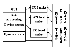
Figure 1 Separation of the traditional parts of an application task
2 DYNAMIC DATA MANAGEMENT AND ORGANIZATION
We use a specialized real time distributed data base management system, SSUDA. It provides 3-D table structures which are placed on the disks of the WSs and in the memory of the FECs and ECs. Table structures are predefined off-line and cannot be changed by applications. Since structures are fixed, the placement of data inside of the data base is calculated by table’s column, row and plane numbers. An application opens the table by name and uses column, row and plane numbers as address values to read/write data. Distribution of the tables is transparent for the applications. All network communications, including EC access, and data transformations for the different types of processors are done by the SSUDA tools and libraries.
The atomic data object (ADO) is a vector, corresponding to technological or physical parameter states. Data objects are combined inside of SSUDA-tables as columns. A data SSUDA-table is a set of ADOs and it contains dynamic data.
Each data object is described by a passport record containing name of ADO, number of vector items, min / max permissible values, etc. Passport records are combined inside of passport SSUDA-tables as rows. So there are three types of SSUDA-tables to serve dynamic data: physical data tables, technological data tables and passports tables.
SSUDA-tables are combined in the data base files. DB files are distributed among the disks of the work stations. Technological data tables are copied from disks into the memory of corresponding equipment controllers.
3 MMI SUPPORT
Only console session tasks support the Man-Machine Interface. There are two console session tasks: one runs in PCs with Microsoft Windows and the other runs in a designated WS with X Window/Motif to serve X-terminals. A session of interaction with the control system consists of two phases: accelerator object/operator task selection and the object/task parameters manipulation.
In the first phase an operator moves over a tree structure of menus described inside of the SSUDA DB. This tree is used to avoid simultaneous setting of correlated parameter values by different operators. Some points of the tree are marked as dangerous so that only one user at a time can proceed further. Dangerous points define the level of user rights to go to the next tree level. Each user of the control system is described in the data base with rights of access to accelerator subsystems.
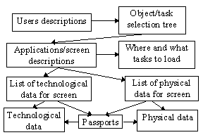
At the end point of the tree a console session task starts the second phase. It initiates the data processing tasks in the different computers in accordance with applications descriptions corresponding to this tree point. From this moment onwards corresponding parameters are shown on the screen as a table. An operator can now edit data and select the form of data presentation, e.g. table, graph, diagram, etc. Figure 2 shows the scheme of MMI data support which is built on the set of SSUDA-tables of well defined structures.
Figure
There are four standard functional windows for user interactions. The first supports the menu tree moves. It is possible to use different forms of presentation of such actions similar to “touch panels”, “file tree” etc. The next one shows physical or technological data as a table. The third is used to show vector values or functional dependencies between different ADOs in the form of graphics and diagrams. The last one is used to output pictures that were prepared by data processing tasks for specific subsystems such as beam diagnostic.
Console session tasks serve an on-line stock of up to 31 accelerator regimes. On operator request, it copies current regime settings to stock or data from stock to the current regime.
4 FRONT END SOFTWARE
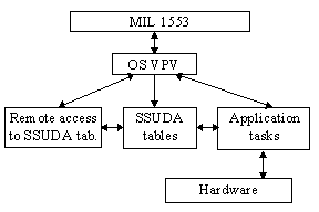
The front end software resides in FECs and ECs. The general functions of the equipment controller’s application software are synchronization with accelerator events, exchange of data between SSUDA data tables and hardware, and monitoring of measurements and hardware states. Figure 3 shows an EC software layout. Application tasks and SSUDA-tables are loaded automatically after EC switch on or reset.
Figure
The general purpose of the FECs is to support communication between computers of the Ethernet level and ECs of the MIL 1553 level. We use the MIL 1553
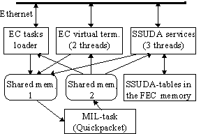
Figure 2 FEC software layout
bus controller drivers and QuickData packets that were developed at CERN [4]. The software is the same for all FECs and permanently serves three base types of protocols: task loading to the ECs, access to SSUDA tables in the memory of FECs and ECs, and virtual terminals of the ECs. Figure 4 shows a FEC software layout. The MIL-task checks periodically for quick packet’s readiness on each EC connected to this FEC.
5 WS LEVEL GENERAL SERVICES
WS level software consists of a console session task, task loaders, SSUDA access services, daemons, and data processing tasks. The main functions of the WS level applications are data processing, transformation of technological data to physical and vice versa, interaction with console session tasks, and EC level applications using SSUDA tables. Figure 5 shows the WS software scheme.
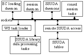
Figure 3 WS level software
Measurements and observation are done by resident tasks continuously providing the data base with current dynamic data. Thus SSUDA DBs present an informational model of the current state of technological processes and hardware in terms of physical and technological values. Each data processing task is initiated with some parameters by the console session task at an end point of the menu tree and deals with the informational model. Task loading is done by sending network requests to the corresponding task loader. Typically, a packet of tasks is loaded to calculate settings. For observation points of the menu tree, the functonalities of the console session tasks are enough.
Global daemons provide full time support of DBs remote access, loading of tasks to ECs on initialization requests, control of all currently opened console sessions and dangerous menu tree points passage, and virtual terminals on any EC. A local task loading server supports data processing task loading for this WS on requests from console session tasks.
6 DATA PROCESSING TASKS STANDARDIZATION
A data processing task may run as (1) a resident task, (2 ) an independent task binding directly to the console session task, (3) the master of tasks packet binding directly to the console session task, (4) a slave of tasks packet binding to packet master task. It’s actions depend on starting parameters.
Standardization has been done in two directions. The first is unification of data sets for communications between different tasks: WS application - EC application, packet slave - packet master, and WS application - console session task. The second is creation of universal tasks such as the packet master, faults analyzer, widely used data processing algorithms realization tasks, etc. This approach integrates all applications as a whole application system with clearly defined interfaces and data processing facilities. It significantly decreases required man power due to using universal tasks everywhere inside of the control system.
It is possible to use technological process modeling tasks inside of an application system. In this case an operator does the usual work with a switched off accelerator and sees the results of modeling. It is a very useful possibility for operator training.
7 PPM SUPPORT
The control system supports pulse-to-pulse modulation (PPM) facilities. On the high level of the CS this requires corresponding number of specimens of settings of physical parameters inside of the SSUDA data bases.
An application in an EC sends new settings to the hardware in accordance with messages from the timing message generator. The technological data are stored as a three-dimensional SSUDA tables in memory of the EC. Each plane corresponds to one logical accelerator. The timing message defines the logical accelerator number (table plane number which is taken as the current accelerator regime).
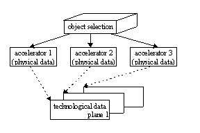
Figure 4 PPM data scheme
The menu tree contains a separate point for each logical accelerator to interact with. The current physical data of the logical accelerator are associated with a certain plane of the technological data table. An operator can modify physical data of different logical accelerators simultaneously. Figure 6 shows the dependencies between the separate tables of physical data and the planes of one table of technological data.
8 REFERENCES
[1] V.Komarov et al. “Upgrading of the U-70 complex controls”, Proceedings of the ICALEPCS’95, Chicago, Illinois, USA, 1995, Vol. 2, p. 930.
[2] V. Komarov et al. “Draft Design Study for the Control System of the U-70 Complex”, IHEP&CERN, CERN internal note: PS/CO/Note 96-26.
[3] V. Voevodin et al. “New Integrated Control System of IHEP Accelerator Complex”, this proceedings.
[4] A. Amundsen et al. “QuickData a new packet type for the M1553B packet protocol”, SL/Note 92-02 (CO)-Rev.,Geneva,1992..